|
Victor — Victrola Motor Identification (and Repair Information)
by Harold Braker
Listed and illustrated in this article are most of
the distinct variations of wind up motors used
in front mount, rear mount, and enclosed-horn
Victrolas. These are the types most commonly found
by collectors. This may not be an exhaustive study but
I hope it will be of interest to those who like to "tinker"
with motors as I do.
Descriptions of "Portables" are lacking due to the
difficulty of finding previously written descriptions and
pictures of them. No one should use this as a "precise
guide" as exceptions to the rule may abound; however,
as a guide to comparison and repair, the collector
should find this of some interest. Some dates and data
have been retrieved from other sources and I cannot
vouch for their correctness. Technical comparisons have
been derived from personal experience, and photos
were personally taken by the author.
I would appreciate contributions from other collectors who can provide pictures and information of other
types of motors which may have been used by the Victor
Talking Machine Co. in Canada and the United States.
I have tried not to repeat in words what is obvious visually.
Fig. 1(A):
Canadian Berliner Model A & D Motor (motor as
shown from a Canadian
version)
U.S.
Victor Model B (Trademark) Sam

|
|
Fig. 1(A) Canadian Berliner Model (A) & U.S. Victor
Model B (Trademark): Unless one possesses a small
lathe and is prepared to make bushings for the gears,
governor pivots, replace the governor drive gear (with a
148-tooth substitute from the Boston or Berg gear companies), the effort often results in a noisy but workable
motor. In any case, just to have a Trademark machine
which is all together, lubricated and working is satisfaction enough.
Figs. 2(B), 3(C) & 4(D): Victor Machine Models C
through Z Motor Type
used I-, 2-, or 3-spring "Spur" or "Brass" motors, as
found in the front mount and early rear mount models.
Although there were differences in gear sizes, barrel
construction, motor frames, governor weights, governor
gears, winding pauls etc., they all had the same style of
gear train with a large noisy governor drive gear. Talko-phone and Victor's Zonophone line used the same
style of motor, except some were improved with quiet
running worm governor gears.
These spur and bevel gear motors, (Figs. 2[B], 3[C]
& 4[D]) are the most challenging of all motors to overhaul satisfactorily but it can be done. Having rebuilt a dozen or more
of this type in Canadian Berliners, I
found these motors were quite poorly manufactured. If
these motors were actually manufactured in the United
States then I am sure most of the following will apply
to early Victors. The main problem is that the stantions
which hold the spring barrel, gears, governor, winding
shaft etc., were not cast as part of the motor frame. As a
result of warped castings, poor machining and hole
drilling, everything is out of alignment and binds when
the stantion mounting screws are tightened. The reason
is that the original factory (or retrofit) shims were made
of paper which are destroyed in the disassembly process, so one has to start from scratch upon reassembly.
Filing of castings, then shimming with shim stock is
often required. This procedure involves rough assembly
of everything (without the spring in the barrel) and
rotating the gears by hand. Obvious misalignment of
the stantions can be seen when visually checking from
all angles, then the necessary filling and shimming is
performed. Final shimming may be necessary after the
bevel gear adjustment. For these gears to run properly,
try to match the previous running position and ensure
there is sufficient but not too much backlash. Check
the backlash every quarter turn.
Fig. 2(B):
Typical single spring motor as found
in Berliner K (Canadian)

|
|
Fig. 3(C):
Typical double spring motor as found
in Victor M

|
|
When you finally get to installing the spring in the
barrel for its first test run, the motor should be off the
motor board and supported somehow in its normal
horizontal position. Final adjustment of the bevel gears
and the governor pinion backlash will provide best
results this way. Because of the value of the machines
(these motors are in) a half-dozen tear downs and
reassembly are worth the frustration to achieve satisfactory performance from these motors. Balancing of governor balls and matchings of governor springs is also a
worthwhile task. I use a 3-beam-gram scale graduated
to 1/100 of a gram, and match each spring to length
and thickness. I do this to any motor from which vibration can be felt. A micrometer or dial calliper is useful
to have for this purpose, as well as for many other
places even if not doing lathe work.
Fig. 4(D):
Typical triple spring motor as found in Victor D and early
Victor VI which was all nickelplated

|
|
Fig. 5(E) Motor Type EM & D: the Victor motor type
EM used in Victor O is similar to motor type D used
in Victor I and shares some of the same parts as the
Victrola IV motor (type B), and all three of these have
the Bull gear as part of the barrel pressing. Two other
similar styles used in Victor I utilise separate but smaller
diameter steel or brass Bull gears (as shown in Figs. 5[E]
and 6[F]), which are riveted or screwed on and may
share the same frame casting with the EM. All of these
styles use 1-inch-wide main springs. Motor Type D as
used in Victor I and Type B as used in the Victrola IV
are similar motors except that the Victrola IV does not
use a geared crank incorporated into the barrel stantion, and has a larger Bull gear than Type EM. Frame
casting appear at first glance to be the same but are not;
the Victrola IV is slightly larger and hole spacings are
further apart. Motor Type CM,also used in Victor O
and Victor
1, is a Victor style all of its own but appears
to share the same brass Bull gear as the other version of
EM and D, except the CM is riveted on, and the other
version of EM and D is held to the barrel with screws
from the wind side flange. As mentioned, the other
Bull gears were not part of the barrel.
Motor Type F Single Spring (see Figs. 8 [5]) is another
one of at least three motor types used in Victor I and
Victrola IV. It also shares some of the parts of the
Victrola type J two-spring motor but not the main
springs, as the type F motor uses a 1-inch main spring.
Fig 7(I) Motor Type BM as used in Victor II, shares
many of the same parts as Victor III and IV. This
motor style, as used in Victor II through VI, was a big
improvement over the "spur" motor and is relatively
easy to overhaul. However, there were some shortcomings in design. For one, when the spring shaft and Bull gear hole wore,
misalignment and poor mesh with the
spindle worm would result, causing wear and damage.
For many of this motor style (which I have yet to repair),
I do not have good replacement Bull gears, so I will
attempt to install the later style Victrola riveted-on
Bull gear, and matching fine pitch worm spindle.
Fig. 5(E):
Motor Type EM as used in Victor I & O (Victor motor
type D is similar as is Victrola Type B)

|
|
Fig. 6(F):
Motor Type CM as used in Victor O & 1

|
|
Fortunately, Victor did convert to a fine-pitch,
6-inch long spindle in later production or were retrofitted.
A better bushing arrangement in barrel drive end, and
the heavier Victrola Bull gear riveted to the barrel, should
result in a longer lasting and more serviceable motor.
Although the course pitch governor gears do not
run as quietly as the fine-pitch ones, these motors per-
form quite well, and should be carefully adjusted with
shim washers so that the barrel (Bull) gear runs properly meshed with spindle, not off the centre line.
Fig. 7(J) Motor Type AM (2-spring) is as used in
Victor III and IV, a modified version is used in Victrolas,
and a third style in early Schoolhouse (XXV), which
had a crank attached directly to the mainshaft.
Fig. 7(K) Motor Type M (3-spring) is used in Victor
V and VI. Also used in Victrolas, some of these motors
having the yielding turntable shaft feature which is
most often found.
Fig. 7(I): as found in Victor II (Type BM)
Fig. 7(J): as found in Victor Ill & IV (Type AM)
Fig. 7(K): as found in Victor V & VI (Type M)

|
|
Depending on the phonograph model — there were
many spindle versions which made them different
from one another — there were at least nine different
lengths and three turntable drive pin locations: 1/2-inch,
7/8 inch and 1 inch below record guide pin. These
variations, I believe, were necessary to fit these motors
into the early Victrolas.
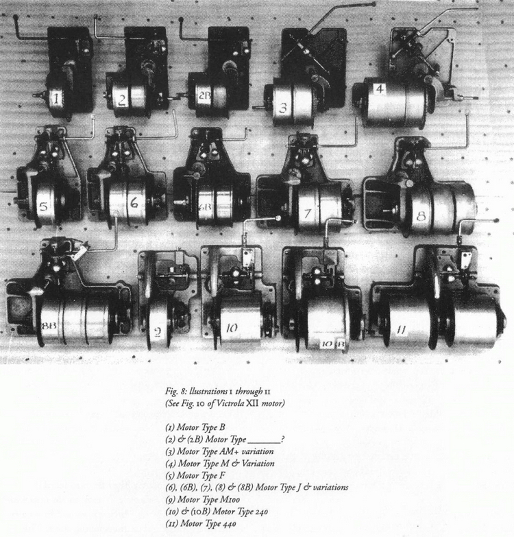
Fig. 8(x) Victrola Motor Type B: Introduced in September
1911, the Victrola IV table model is powered
by a 1-inch main spring which was wound by an arbor
shaft directly attached to the winding crank. This
motor appears to have been used in an intermediate
model Victor I (type D) around the same time, but
with a geared crank built into the barrel stantion. Another
similar style, as described earlier, was used in the small
case Victor I (type EM) which had a smaller diameter
brass Bull gear, which would only fit into its own case.
Figs. 8(2) & 8(2B) Victrola Motor Type 2:
Introduced October 1911 in Victrola VI, and Victrola
VIII in September 1911 (and others?), but with two 1-inch
main springs, this model used a geared crank built into
the main frame, which raised the crank up. Figure 2B is
similar, except it is without a geared crank. The spring
is wound directly with a crank screwed to the spring
shaft on the other side, resulting in a lower positioned
crank. It is not known if this style motor was used in
horn machines.
Fig. 8(3) Motor Type AM & Variations: This motor is
equipped with 1.25-inch wide springs, and appears to be
an adaptation of the Victor III motor, with the geared
crank winding from the other side. The later Victor III
used the notched motor frame designed for the Victrola
application. A third style of this motor was used in the
Schoolhouse which had the crank screwed directly to
the spring shaft.
Fig. 9:
A different example of a single spring "spur" motor with an all-iron top

|
|
Fig. 8(4) Type M & Variations: This early Victrola
motor was directly interchangeable with the Victor V
and VT (except earliest spur gear models), and the model
which had the crank attached directly to the spring shaft.
Most of these motors had the "yielding" shaft feature
and cast iron turntable. Later model Victors and Victrolas
did away with this feature, using the more common
slip-on pressed-steel turntable. This motor used three
1.25-inch springs and used the same 6-inch long spindle
worm shaft as (3) above. Fine thread barrel and governor
gears were used on later versions resulting in quieter
running (Retrofit 2?)
Listed and pictured are most of the variations of
motors used in Victrolas. (See Fig. 10 of Victrola XII
motor shown separately.)
Figs. 8(5-8B) Victor and Victrola Type E J and Variations
(some used in the very last horn machines): This series
to 8(8B) are similar styles, except that (5), (6) and (6B)
have 1-inch mainsprings and (7), (8) and (8B) have 1.25-
inch springs. Also, (6), (7) and (8B) have geared cranks,
while (5), (6B) and (8) have cranks attached to the spring
shafts on the opposite sides. Figure 8(7) is a Victrola
type J introduced November 1st, 1914 and uses the same
main-spring as types M and AM. It may be that each of
these motors has a version which could be wound from
the other side. More research is needed here.
Note: (6B) was removed from a table model inside
horn Zonophone machine (No. 1126). No. (5) appears
to be the type F as used in a late model Victor 1 and
No. (6) I believe I saw in a very late model Victor II
when visiting Musical Americana some years ago. This
Victor II also had an aluminum I.D. plate with Roman
numerals.
Fig. 10:
Victrola XII motor (Unique Victor)

|
|
Of the preceding purely Victrola motors (years 1911
to 1917 approximately) all these housed a single spring
in a single barrel arrangement, and the governors
angled downwards. With the governor friction disc
hanging down, one would think that the governor
would have to work harder to pull the friction disc up
against gravity. The Bull gears were similarly attached
to spring barrels with rivets, except now the spring shaft
and supporting bushings were significantly improved
making this style a much longer wearing design. Does
anybody know of a 3-spring version using 1-inch
springs which is not the spur type? Anyhow, it would
be interesting to know why the later motors went back
to horizontal governors and with larger worm diameters.
Figs. 8(9), (10), (10B), (11) Victrola Motor Type M-
100, M-240 M-440 etc: This series appears to have
been used in all later model Victrolas introduced June,
1917 and all having 1.25-inch springs except the single
spring version which used a 1-inch spring. Governors
are mounted horizontally as the earlier rear mount horn
machine models. The governor worm gear is slightly
larger in diameter from .280 inches to .310 inches
(appear not interchangeable?); however, the numbers of
teeth remained the same. (9), (10), (10B) and (11) Bull
gears are spring driven and all the other prior models
are barrel driven. Motor (10B) used bent-end springs
and had a different winding dog and pawl arrangement. Speed indicator attachments may have been on
more models than is evident in the pictures.
Notes on Lubrication
All moving metal parts require lubrication to prevent
wear and reduce friction. Modern automobile engines
and gear trains last so much longer than their counter-
parts prior to the 60s. This is due mainly to superior
lubricants being made today, so, the phonograph can
benefit from their use also.
- Mainsprings
I have used the modern substitute Molybdenum® disulphide for the original graphite grease. This is a multipurpose grease in a non-melt base made by Moly Slip®
and others. I have used this in dozens of motors over
the years and never experienced chugging or thumping,
as | have with oils or white grease. Moly Slip® has a
very fine buttery texture and spreads easily around the
coils after the barrelis closed up.
- Gears and Pivots
Extreme pressure (EP) automotive gear oils work best
in the slow moving areas of high pressure between
gears, pivots and shafts. There is no gear so perfectly
made that sliding between gear teeth does not occur,
and even more so once teeth wear a little, so lubrication
is essential. With most phonograph motors totally
enclosed and suspended under the motor board, contamination
of oils is not a factor to worry about. Avoid
oils and greases which dry out after application (e.g.,
wax base oils).
- Governors
Suitable oils for governor friction discsd top works
of cylinder machines need a light non-wax oil. I use
SAE 20 refrigerant oil which has no wax therefore will
not get sticky or dry out quickly. Light household and
automotive oils serve well in this area also.
About the Author
Having recently retired, I now have the time to work
on restoring my collection of cylinder and disc
machines. I started collecting phonographs in 1968, and
doing repairs for other collectors — but only quality
repairs. If a gear pivot was worn on a shaft end, a new
oversize pivot was machined in and the worn pivot hole
was centred and reamed out to fit, or rebushed with
brass bushing, in the same manner that clock repairs
are done,so that proper gear contact and backlash are
maintained.
I was fortunate to have found and purchased two
warehouse stocks of new and used phonograph parts,
one cache in 1973 weighing 1,850 lbs. While travelling
on business all over the Canadian Prairies, it took me 3
years to track down this cache after hearing from another
collector that a Port Coquitlam, British Columbia music
store had many years prior sold all their old stock of
crated machines and parts to an unknown collector in
the Prairies somewhere. I did not know for sure that
this was the collection I had heard about till I began
unwrapping the sealed boxes at home and discovered the
parts all wrapped in a 1942 Port Coquitlam newspaper.
The other find was in 1974, nearly 1,000 lbs of new
boxed main springs, gears, governor springs, reproducers,
etc. This find came from a music store in Winnipeg
which was still selling wind up phonographs and 78
RPM records displayed in the store at the time (1974),
however the parts were neatly stacked in the warehouse
untouched for 40 to 50 years, as were thousands of
parts for musical instruments. It was hard to believe
what I saw. Another deal was made and from the two
collections for the next 18 years I sold and traded my
surplus parts to other collectors. Finally, in February
1992, the last of my surplus Edison gears (mostly new
old stock) were traded off.
I have started to make patterns for casting reproduced
back brackets and jigs to make wood horns in the years
to come. If ever time permits I hope to do a similar
study of Columbia motors as I have with Victor, and if
somebody wants to collaborate or undertake this project,
I would be glad to assist in the effort.
|